
Explain the different design principles used in an enterprise network
High-level enterprise network design such as 2-tier, 3-tier, fabric, and cloud
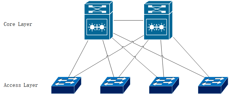
2-Tier Architecture
- Core Layer: Responsible for high-speed processing and forwarding of data, often involving high-capacity backplanes and connections to support the data flow throughout the entire enterprise network.
- Access Layer: Connects directly to end-user devices (such as workstations, printers, etc.), serving as the entry point for users accessing network resources.
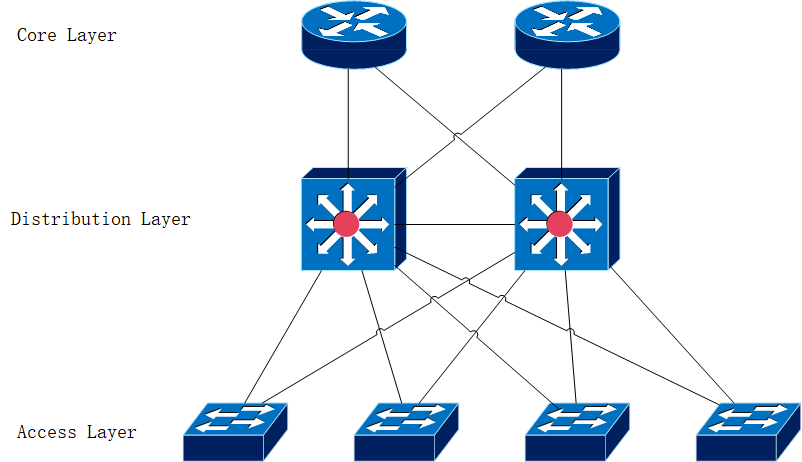
3-Tier Architecture
The 3-Tier architecture adds a distribution layer (or aggregation layer) on top of the 2-Tier model, dividing the network into three layers: core, distribution, and access.
- Core Layer: Responsible for high-speed processing and forwarding of data, often involving high-capacity backplanes and connections to support the data flow throughout the entire enterprise network.
- Distribution Layer/Aggregation Layer: Acts as an intermediary between the core and access layers, providing routing, filtering, and VLAN (Virtual Local Area Network) segmentation, adding flexibility and control to the network.
- Access Layer: Connects directly to endpoints (such as hosts, printers, servers, etc.), serving as the entry point for users accessing network resources.
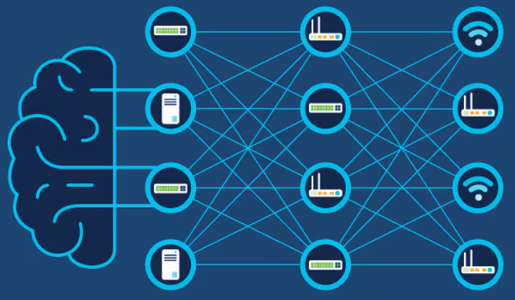
Fabric
Fabric refers to the mesh of connections between network devices (such as access points, switches, and routers) used to transport data to its destination. While "fabric" sometimes also refers to the physical lines that make up these connections, it is more commonly a virtualized, automated overlay mesh superimposed on the physical topology.
- It typically involves treating network devices and resources as a unified Fabric (literally meaning cloth, understood as an interwoven network), where data can enter and exit at any point, dynamically routed through the best path.
- Fabric is particularly suited for data centers and cloud environments, as it can effectively handle large volumes of dynamically changing traffic patterns and application demands.
Cloud
Cloud architecture outsources part or all of an enterprise-level network's infrastructure to cloud service providers, delivering services and resources over the internet.
- This design allows enterprises to leverage the scalability, elasticity, and cost-effectiveness of cloud computing, supporting a variety of applications from Infrastructure as a Service (IaaS) to Platform as a Service (PaaS) and Software as a Service (SaaS).
- Cloud architecture also supports rapid deployment and management of applications, as well as access by users distributed globally, making it an essential component of modern enterprise network design.
High availability techniques such as redundancy, FHRP, and SSO
Redundancy
Redundancy is a fundamental principle of high availability design, referring to the presence of additional or backup components, devices, or connections in a system that can take over when primary elements fail, thus maintaining service continuity. Redundancy can be applied at different levels, including hardware (such as servers, switches, routers), network connections, power supplies, and storage. By creating redundant paths, data can flow through an alternate route if one fails, thereby reducing the risk of a single point of failure.
First Hop Redundancy Protocol (FHRP)
First Hop Redundancy Protocols (such as HSRP, VRRP) are among the advanced strategies for implementing redundancy in a network, designed to ensure the continuous availability of routers or switches. These protocols allow multiple devices to share a virtual IP address and MAC address. In the event of a primary device failure, a backup device can quickly take over, ensuring uninterrupted network traffic. FHRP enhances network stability and reliability by providing seamless failover between critical devices.
Stateful Switch Over (SSO)
When discussing high availability, SSO typically refers to Stateful SwitchOver, not Single Sign-On, which is a high availability technology used in network devices (such as routers and switches) as well as servers and applications. SSO allows for seamless switching between primary and backup systems upon failure of the primary system, while maintaining active session and state information. This means that during the failover process, end-users experience minimal disruption, as the backup system takes over all active sessions and state information, continuing to process requests as if no switch had occurred.
Describe wireless network design principles
Wireless deployment models (centralized, distributed, controller-less, controller-based, cloud, remote branch)
Wireless deployment models define the architecture and management style of wireless networks. The main models include:
- Centralized: In this model, all APs are connected via a wired network to a centrally deployed controller. This model is suitable for deployments within a campus or a single large building, facilitating centralized management and deployment.
- Controller-based: Similar to centralized, this model relies on one or more physical or virtual controllers to manage the network. Controllers handle tasks such as authentication, policy enforcement, and client roaming.
- Distributed: In a distributed model, each access point handles the forwarding of data frames independently, without the need for a central controller. This model is suitable for environments with geographic dispersion and multiple nodes, such as multiple offices or retail stores.
- Controller-less: In a controller-less model, access points do not rely on an external controller for communication management. Each AP is self-managed, simplifying the network's configuration and expansion.
- Cloud: The cloud model hosts the controller functions on a cloud platform via the internet. This provides flexibility and scalability for management while reducing the need for local hardware.
- Remote Branch: This model is suitable for deployments in remote or branch offices, often combining centralized and cloud models to manage and control the wireless network of the branch offices.
Location services in a WLAN design
Location services use a Wireless Local Area Network (WLAN) to determine the physical location of devices, which is crucial in many applications, such as asset tracking, indoor navigation, and context-aware services. When designing a WLAN with location services, consider the following aspects:
- AP Layout: To accurately locate devices, APs should be evenly distributed, covering all areas while overlapping coverage redundantly.
- Signal Strength and Quality: Location accuracy depends on the strength and quality of the signal. The design should consider physical obstacles and environmental interference.
- Software and Hardware Support: Using specialized location engines and hardware that supports location services can improve accuracy.
Client Density
Client density refers to the number of devices connected to the network in a specific area simultaneously. High client density can significantly impact network performance, necessitating special design considerations to cope:
- High-Density AP Deployment: Increase the number of APs in high-traffic areas to alleviate the load on each AP.
- Use of Directional Antennas: Directional antennas can help APs direct signals to specific areas, thus reducing signal interference and enhancing performance.
- MIMO (Multiple Input Multiple Output): MIMO technology increases the transmission capacity of each AP, improving network performance.
- Band Management: Use dual-band or tri-band APs (supporting 2.4GHz and 5GHz) to optimize spectrum usage.
- Quality of Service (QoS) Policies: Implement QoS policies to ensure the performance of critical applications is not affected by high traffic.
Explain the working principles of the Cisco SD-WAN solution
SD-WAN control and data planes elements
- Control Plane: The control plane is responsible for building and maintaining the network topology and deciding the direction of traffic flow. In Cisco SD-WAN, the vSmart controller is the central component of the control plane, handling the delivery of routing information, policies, and configurations to guide the paths of packets across the network, helping to improve the network's flexibility and response time to changes in network conditions.
- Data Plane: The data plane is responsible for forwarding packets based on the decisions made by the control plane. In Cisco SD-WAN, this is managed by vEdge devices, which handle the forwarding of packets, including encrypting and decrypting packets to ensure secure data transmission.

- Management Plane: Handles centralized configuration and monitoring. In Cisco SD-WAN, this is achieved through the vManage, a centralized management component, allowing network administrators to configure policies, monitor network status, and troubleshoot management operations.
- Orchestration Plane: Assists in automatically integrating SD-WAN routers into the SD-WAN network. In Cisco SD-WAN, this is typically accomplished through the vBond orchestrator, which manages device authentication, inter-device connections, and the establishment of encrypted channels.
Benefits and limitations of SD-WAN solutions
Advantages
- Enhanced Network Agility: Cisco SD-WAN offers dynamic path selection features that automatically choose the best paths based on real-time network conditions, improving application performance and user experience.
- Centralized Management: Through a centralized management platform, remote configuration and monitoring of all network devices are significantly simplified, greatly easing network operations and maintenance.
- Excellent Scalability: The separation of the control and data planes allows for easy expansion and deployment, and upgrades at any level do not affect the ongoing operations of the current network.
- Cost-Effectiveness: SD-WAN can utilize internet links, reducing dependence on expensive dedicated lines (such as MPLS), thereby lowering network costs.
- Improved Security: Integrated security features, such as encryption and granular access control policies, enhance the security of the network.
Limitations
- Initial Deployment Costs: Although there are long-term cost savings, the initial costs for equipment and deployment can be relatively high.
- Complexity: Deployment and management of SD-WAN may require new skills and training for traditional network operators.
- Dependence: Typically, SD-WAN solutions are integrated by vendors, which cannot be easily migrated to other vendors.
Explain the working principles of the Cisco SD-Access solution
Cisco SD-Access (Software-Defined Access) is a solution aimed at simplifying enterprise network operations, enhancing security, and increasing network flexibility. It is part of Cisco's Digital Network Architecture (DNA) and is primarily used in campus networks.
SD-Access control and data planes elements
- Control Plane: Responsible for communication and message transfer between infrastructure devices within the Fabric, primarily based on LISP (Locator/ID Separation Protocol).
- Data Plane: Responsible for executing the policies defined by the control plane and handling data encapsulation and forwarding. Primarily uses VXLAN technology to encapsulate traffic, supporting flexible network segmentation and optimized path selection across multiple physical locations.
- Policy Plane: Handles security policies and segmentation, mainly based on Cisco TrustSec, including ISE (Identity Services Engine), among others.
- Management Plane: Handles orchestration and management, primarily based on Cisco DNA Center.
Traditional campus interoperating with SD-Access
- Gateway Interoperation: Establishing interoperation gateways between SD-Access and traditional networks allows for smooth data exchange between different architectural segments. This is usually achieved by configuring specific routing and security policies.
- Policy Consistency: Ensuring consistency of security and access policies during the migration or expansion from traditional networks to SD-Access. This involves complex policy management and meticulous configuration in the DNA Center.
- Gradual Deployment: Enterprises can opt for a gradual deployment strategy, where part of the network uses SD-Access while part remains in the traditional architecture. This approach can mitigate migration risks while validating the effectiveness of the new solution.
The primary purpose of SD-Access is to provide a more secure, flexible, and easily managed network access method. By using policy-driven access control and automated network management, SD-Access helps enterprises achieve the following goals:
- Enhanced Security: By implementing fine-grained user and device-level policies, network security is enhanced.
- Simplified Operations: Automated configuration and management reduce the complexity of network operations.
- Better Performance and Reliability: Optimized path selection and network resource management improve the overall performance and reliability of the network.
Interpret wired and wireless QoS configurations
QoS components
In wired and wireless networks, QoS components mainly include the following aspects:
- Classification and Marking: Traffic is identified and classified according to its type (such as voice, video, or data). It is then marked according to its importance and service requirements for recognition by network devices. Common marking techniques include IP Precedence and DSCP (Differentiated Services Code Point).
- Queuing: Traffic is placed into different queues, each queue being assigned a different processing priority based on its QoS requirements. For example, voice communications, being sensitive to delays, are typically placed in the highest priority queue.
- Congestion Management: When network resources are insufficient to handle all traffic, congestion management strategies determine which packets are sent first and which are delayed. Common congestion management algorithms include Tail Drop, Random Early Detection (RED), and Weighted Random Early Detection (WRED).
- Traffic Shaping and Policing: Traffic shaping smooths out data flows to avoid bursts, while rate limiting enforces that data flows do not exceed a set rate. These controls help prevent network overloads and ensure that various traffic types receive appropriate bandwidth.
QoS policy
Designing and implementing a QoS policy involves the following key aspects:
- Policy Definition: Clearly define which businesses and applications require special QoS handling, such as real-time voice and video communications that need priority processing to ensure communication quality.
- Device Configuration: Implement QoS configurations on routers, switches, and other network devices. This includes setting up classification, marking, queuing policies, congestion management, and traffic shaping.
- Monitoring and Adjustment: Implementing a QoS policy is not a one-time task. Changes in network conditions and the evolution of business needs require continuous monitoring of QoS performance and adjustments to policies as needed.
- Cross-Platform Consistency: In mixed environments (e.g., networks with both wired and wireless devices), ensuring consistency of QoS policies across different platforms and devices is crucial.
Describe hardware and software switching mechanisms such as CEF, CAM, TCAM, FIB, RIB, and adjacency tables
CEF (Cisco Express Forwarding)
CEF is a fast forwarding mechanism used in Cisco routers to enhance network efficiency. It utilizes two main data structures: the Forwarding Information Base (FIB) and adjacency tables.
- FIB (Forwarding Information Base): The FIB contains a copy of the IP routing lookup table, used to determine the forwarding of packets. It is generated based on the Routing Information Base (RIB), but only includes the best paths and necessary information to optimize forwarding performance.
- Adjacency Tables: Adjacency tables store the link-layer address information of the next-hop routers, which is necessary to forward packets directly to the next device.
RIB (Routing Information Base)
The RIB is a table in routers that contains all routes learned from different routing protocols (such as BGP, OSPF, etc.). The RIB includes all known paths and their attributes in the network, and the routing algorithm selects the best paths from these to push to the FIB for data forwarding.
FIB (Forwarding Information Base)
The FIB is a simplified table of the best routes selected from the RIB, specifically used for the fast forwarding of packets. The FIB directly relates to packet processing and forwarding, containing the address information of the next hop.
Adjacency Tables (Adjacency Tables)
The adjacency table is an important component used by CEF, recording interface information of directly connected devices. This table ensures that packets are correctly encapsulated and sent to the next hop device.
CAM (Content Addressable Memory) and TCAM (Ternary Content Addressable Memory)
- CAM: Used in network devices to store information, such as Ethernet MAC addresses. CAM allows for fast content-based searches, enabling switches to quickly match specific MAC addresses and decide how to forward frames.
- TCAM: Compared to CAM, TCAM provides more advanced lookup capabilities, storing data in three states: 0, 1, and "don't care" (X). This makes TCAM very suitable for storing complex network policies and advanced routing lookups, such as Access Control Lists (ACLs) and QoS policies.
During the entire packet forwarding process, they work together to achieve efficient and accurate network operations. When packets arrive at a device, the FIB (processed quickly by CEF) first determines the forwarding decision, followed by the adjacency table to look up the data link layer address, and finally, CAM or TCAM performs fast hardware-level forwarding. This mechanism significantly improves data forwarding efficiency and performance in large network environments.
Reference materials:
https://www.cisco.com/c/en/us/td/docs/solutions/Enterprise/Campus/campover.html
https://www.cisco.com/c/dam/global/shared/assets/pdf/cisco_enterprise_campus_infrastructure_design_guide.pdf
https://www.cisco.com/c/dam/en_us/solutions/industries/docs/education/cisco_wlan_design_guide.pdf
https://www.cisco.com/c/en/us/solutions/design-zone.html#~guides-by-technology
https://www.cisco.com/c/en/us/td/docs/solutions/CVD/SDWAN/cisco-sdwan-design-guide.html#Introduction
https://www.cisco.com/c/en/us/td/docs/solutions/CVD/Campus/cisco-sda-design-guide.html